
2015-02 Upconverter, 70 MHz to 950-2150 MHz
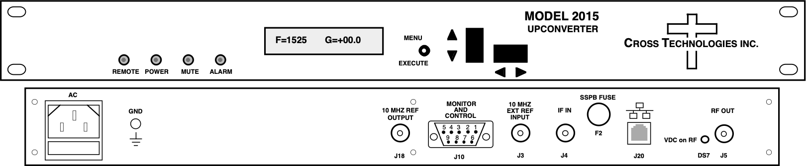
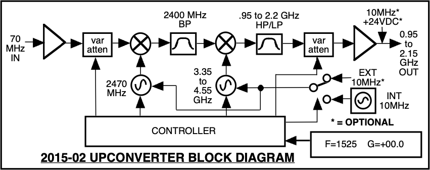
The 2015-02 L-band Upconverter converts 70 ± 18 MHz to 950 to 2150 MHz in 1 MHz steps (125 kHz to 1 kHz step options available). Synthesized local oscillators (LO) provide frequency selection. Push button switches select the RF frequency, gain, and other parameters. Front panel LEDs provide indication of DC power (green), PLL alarm (red), remote operation (yellow) and TX carrier MUTE (yellow). Variable attenuators for the IF input and output provide a gain range of -10 to +30 dB as adjusted by the front panel push-button switches. Remote operation allows selection of frequency and gain. Parameter selection and frequency and gain settings appear on the LCD display. Connectors are BNC female for IF and the optional external reference input and output, and Type F female for the RF output. SSPB +24 or +48 VDC and 10 MHz reference can be inserted on the RF line as added options. The external 10 MHz option E includes a 10 MHz output connector which contains either the internal or external 10 MHz reference signal. A high stability internal reference (option H, ±0.01ppm) is also available. It is powered by a 100-240 ± 10% VAC power supply, and housed in a 1 3/4” X 19” X 16” rack mount chassis.
| Impedance/Return Loss | 75 Ω / 18 dB |
| Frequency | 70 ± 18 MHz |
| Input Level | -40 to -10 dBm |
| Impedance/Return Loss | 75 Ω / 12 dB |
| Frequency | 950 to 2150 MHz |
| Output level | 0 to -20 dBm |
| Output 1 dB compression | +5 dBm |
| Gain range (adjustable) | -10.0 to +30.0 dB, 1 ±1 dB steps |
| Frequency Response | 1.5 dB, 950-2150 MHz; ±0.5 dB, 36 MHz BW; ±1.0 dB, 40 MHz BW |
| Spurious Response | < -50 dBC, in band |
| Group Delay (max) | 0.015 ns/MHz^2 parabolic; 0.05 ns/MHz linear; 1 ns ripple |
| Frequency Sense | Non-inverting |
| Frequency Accuracy | ±1.0 ppm max over temp (±0.01 ppm, option H) |
| Frequency Step | 1.0 MHz (125 kHz to 1 kHz step options available) |
| 10 MHz Level (In or Out) | 3 dBm, ± 3 dB, 75 Ω (option E) |
| Frequency | Phase Noise |
|---|---|
| 10 Hz | -55 dBC/Hz |
| 100 Hz | -70 dBC/Hz |
| 1 kHz | -70 dBC/Hz |
| 10 kHz | -80 dBC/Hz |
| 100 kHz | -90 dBC/Hz |
| 1 MHz | -110 dBC/Hz |
| <none> | |
|---|---|
| Freq/Gain Selection | Direct readout LCD; manual or remote selection |
| Power; Alarm; Remote; Mute | Green LED; Red LED; Yellow LED; Yellow LED |
| Remote | RS232C, 9600 baud (RS485, Ethernet Optional) |
| <none> | |
|---|---|
| RF / IF Connectors | Type F (female) / BNC (female) |
| 10 MHz Connectors | BNC (female), 75Ω (option E - works with 50Ω or 75Ω) |
| Alarm / Remote Connector | DB9 (female) - NO or NC contact closure on Alarm |
| Size | 19" 1RU standard chassis, 1.75”H X 16.0”D |
| Power | 100-240 ±10% VAC, 47-63Hz, 25W max (24VDC and 48VDC optional) |
| <none> | |
|---|---|